Digital implant impressions are only as accurate as the small component that “translates” implant position into a file your lab can design from: the implant scan body. When an implant scan body is not fully seated, is under-tightened, over-tightened, contaminated, rotated, or scanned incompletely, the downstream consequences can be expensive—misfit frameworks, occlusal surprises, remakes, and hours lost to troubleshooting.
That’s why scan body torque and scan body handling should be treated like a clinical procedure, not a casual step. Research continues to show that scan bodies and their characteristics (material, geometry, height, and how they are handled) can influence scanning accuracy, and that factors like torque and even sterilization can affect how a scan body seats or displaces.
This article gives you a repeatable, chairside checklist to reduce scan body indexing errors, protect implant library accuracy, and improve predictability—especially for multi-unit and full-arch cases where small errors accumulate. It is written to be accessible for the whole team (doctor, assistant, and front desk) while remaining detailed enough for high-level implant workflows.
What an implant scan body actually does
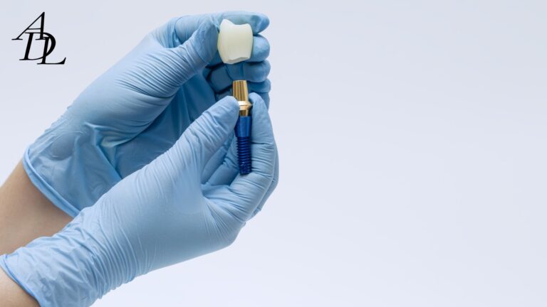
An implant scan body is a prefabricated component placed on an implant or abutment that provides a known geometry. Your scanner captures that geometry; your CAD software then matches it to a digital library file to locate the implant’s 3D position and orientation.
That last step is where implant library accuracy lives or dies. If the captured scan body shape is incomplete or distorted, the software’s “best match” can be wrong—even if it looks okay on screen. Studies show that scan body image deficiencies and improperly scanned scan bodies can produce registration errors in virtual implant positioning.
The clinical takeaway is simple: your implant scan body is not a passive accessory. It is a measuring instrument. Treat it accordingly.
Why scan body torque matters more than people think
It’s easy to assume scan body torque is just about “keeping it from falling off.” But torque (and the act of tightening) can influence seating and micro-position.
Here’s what current evidence suggests:
- Tightening torque can influence scan body displacement or subsidence during screw tightening, with factors such as scan body material and sterilization also playing roles.
- Research evaluating tightening torque effects has documented measurable deviations associated with torque application and seating behavior of implant scan bodies.
This doesn’t mean you should “crank it down.” It means you should apply scan body torque consistently within the manufacturer’s limits and confirm seating every time.
The real goal of scan body torque
The goal is not maximum torque. The goal is repeatable, full seating without rotation or vertical gap, using the manufacturer-recommended approach (often “hand-tighten,” sometimes a specified maximum torque).
Manufacturer instructions vary:
- Some systems instruct clinicians to hand-tighten the scan body and ensure proper alignment before tightening.
- Some scanbody IFUs specify a maximum tightening torque (for example, a max of 15 N·cm) and warn not to rotate the scanbody during scanning once installed.
So the best practice is: follow the IFU for that specific implant scan body, and standardize your team’s tools and habits around it.
The three categories of scan body problems you’re trying to prevent
Most “bad implant scans” fall into one (or more) of these buckets:
1) Seating and indexing errors
- Soft tissue trapped under the implant scan body
- Not fully seated (vertical gap)
- Rotational mis-indexing
- Wrong platform/connection (scan body compatibility issue)
2) Handling and tightening errors
- Under-tightening leading to micro-movement during scanning
- Over-tightening causing displacement, subsidence, or component damage
- Damaged scan body screw or worn driver engagement
3) Data capture and library errors
- Scan body not fully captured (missing faces)
- Scan stitching drift in full arches
- Wrong library version or wrong scan body selected in CAD
- Mixing brands (physical scan body from one manufacturer, library from another)
The good news: the checklist approach below addresses all three.
The Scan Body Torque & Handling Checklist
Step 1: Before you open the implant scan body package
This is a two-minute setup that prevents 30-minute rescue appointments.
Confirm scan body compatibility
- Confirm implant brand and platform (and whether you are scanning implant-level or abutment-level).
- Confirm the exact scan body part number and height.
- Confirm whether it is intended for intraoral scan bodies (chairside) vs laboratory scan bodies (model scanning).
Manufacturers emphasize using the correct scan body and following scanning instructions for the planned restorative procedure; this is not optional in modern digital workflows.
Inspect the implant scan body and screw
Check for:
- rounded screw head/driver interface
- chipped scan body geometry
- worn flats or reflective damage
- cracks in PEEK/plastic bodies
- debris in the screw channel
If any defects are present, replace it. Inaccurate geometry defeats the purpose of the implant scan body.
Confirm your tightening tool chain
- Correct driver for that scan body screw
- A calibrated torque wrench if the IFU requires a defined scan body torque
- A consistent “where do we set it?” policy (team standard)
Some guidance documents specifically warn about overtightening risks and give target ranges such as 10–15 N·cm for certain scan bodies when using a manual torque wrench.
Step 2: Seat the implant scan body like you’re seating a crown
A scan body is a seating procedure, not just a placement.
Tissue management
- Control bleeding and fluid (gentle retraction; hemostasis as needed).
- Suction and dry the connection and surrounding tissue.
- Confirm there is no tissue “draping” between the scan body and the implant interface.
Why it matters: soft tissue interference can create a vertical gap or tilt that looks minor but becomes a millimeter-level occlusal error in a full-arch framework.
Visual alignment before tightening
Many manufacturers explicitly instruct aligning the parts first, then tightening—especially for scan bodies with indexed orientation features.
Practical tip:
- Seat the scan body fully first.
- Only then begin tightening.
- Do not use tightening as a way to “pull it down” into place if it isn’t already seated.
Apply scan body torque correctly
Your rule should be: “tighten to IFU, never beyond.”
Typical patterns you will see in IFUs and guidance:
- hand-tighten only (common in several implant system workflows)
- a defined maximum scan body torque such as 15 N·cm (example from a scanbody IFU)
- a safe tightening range such as 10–15 N·cm (example support guidance for certain coded scan bodies)
Clinical reality:
- Under-tightening can allow micro-rotation or micro-lift during scanning.
- Over-tightening can damage screws or alter seating behavior and can contribute to displacement during tightening, as some research indicates torque influences scan body displacement.
Verify no rotational or vertical looseness
A manufacturer step-by-step guide for scanbodies recommends checking for proper fit and for any rotational or vertical looseness after placement, and then hand-tightening.
Do this check every time:
- Attempt gentle rotational movement with a cotton plier (do not distort plastic).
- Confirm the scan body sits flush without a visible gap.
Radiograph when the case demands it
For single units with great visibility, you may not always need a radiograph. For deep tissue, limited access, or high-consequence multi-unit cases, a quick PA can prevent a major remake. Many clinical protocols recommend radiographic confirmation of complete seating for implant components in certain workflows.
Step 3: Scan body handling rules during scanning
Once the implant scan body is seated and tightened, your next job is not to disturb it.
Do not rotate the scan body after installation
Some scanbody IFUs explicitly warn not to rotate the scanbody during scanning once it has been installed.
Keep it dry and readable
- Dry the scan body surfaces before capturing.
- Control saliva and fogging.
- Avoid reflective artifacts if your scanner is sensitive.
Avoid “touch corrections”
Do not use fingers or instruments to “nudge” the scan body mid-scan. If you suspect movement, stop, remove the scan, and restart after verifying seating and scan body torque.
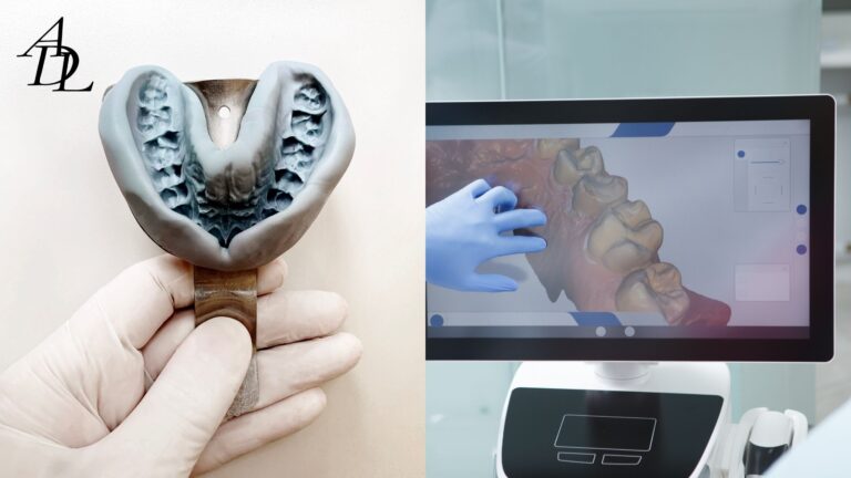
Step 4: Data capture checklist for intraoral scan bodies
Even perfectly seated scan bodies can produce errors if the scan is incomplete.
Capture all the geometry the software needs
The software matches the captured mesh to the library. If you miss key faces, the match can be wrong.
Evidence supports this:
- Improperly scanned scan body data can negatively affect the accuracy of virtual implant positioning due to incorrect scan body image matching.
- Scan body image capture deficiency and scan body exposure levels influence virtual implant position accuracy in CAD alignment studies.
Practical standard:
- Capture 360° around the scan body when possible.
- Ensure the top and at least two side faces are clearly captured.
- Re-scan immediately if you see holes, tearing, or “melted” mesh.
Confirm scan body exposure is adequate
If tissue is covering most of the scan body, accuracy drops. This is especially important for deep implants or subgingival platforms. The PLOS One study specifically evaluated different exposure scenarios (full, 2/3, 1/3 exposure) and showed that exposure deficiency affects accuracy.
Step 5: Full-arch implant scanning tips (where errors compound)
Full-arch implant cases magnify drift. Small stitching errors accumulate over distance, and long edentulous spans reduce unique landmarks for the scanner to “lock onto.”
Associated Dental Lab’s scan stitching error guide summarizes practical de-risking tactics for full arches:
- anchor early and often to recognizable landmarks
- build cross-arch overlap rather than a long “string-line” path
- segment your route with deliberate overlap
- add angled passes across edentulous spans to introduce geometric variety
Research supports the broader point: complete-arch digital implant impressions remain more challenging than short spans, and accuracy varies by scanner and workflow.
Full-arch implant scanning checklist
- Place and verify every implant scan body (seating + scan body torque + no looseness).
- Capture a stable reference: remaining teeth, palatal rugae, or other landmarks early.
- Use a segmented scan path with overlap (posterior → anterior → posterior).
- Re-scan small corrupted zones rather than “pushing through” drift.
- Capture the scan bodies from multiple angles to avoid shadowing.
- Verify the digital model: look for warpage across the arch (distances that “look wrong”).
Consider hybrid workflows for high-stakes full arches
Associated Dental Lab specifically recommends a hybrid approach for complex full-arch fixed cases (digital scan plus verification strategy) to reduce cross-arch error before final.
Peer-reviewed work also shows that implant libraries and intraoral scanners influence the trueness of digital impressions for full-arch implant prostheses—meaning your implant library accuracy and software chain matter more in full arches than in single units.
Step 6: Implant library accuracy and scan body compatibility checks
A scan can be “clean” and still be wrong if the library match is wrong.
What causes scan body indexing errors in software
- Wrong scan body selected in CAD
- Wrong implant system library or wrong platform size
- Outdated library version (mismatch between scan body revision and CAD file)
- Mixing physical scan bodies across brands with the “closest” library
Research confirms that the implant library itself can affect the trueness of full-arch digital impressions, reinforcing that implant library accuracy is not a minor administrative detail.
Practical rules for scan body compatibility
- Use the scan body designed for the implant system and platform.
- Use the matching library recommended by the manufacturer or your lab’s validated library set.
- Document the exact scan body used (brand, platform, height) on the Rx.
Associated Dental Lab explicitly advises clinicians to list the implant brand, platform, and the exact scan-body/library on implant prescriptions to avoid delays and mismatches.
Troubleshooting: fast fixes when something looks off
Problem 1: The scan body looks seated, but the restoration is consistently off
Likely culprits:
- micro-gap not visible clinically
- tissue trapped under the scan body
- scan body torque not applied consistently
- scan body moved during scanning
- incomplete scan body capture leading to library misfit
Fix:
- remove and re-seat the implant scan body
- dry, inspect, and re-tighten to IFU
- radiograph if access is limited
- re-scan and ensure full scan body geometry capture
Problem 2: Full-arch fit issues even with “good” scan bodies
Likely culprits:
- stitch drift
- inadequate landmarks
- long edentulous spans
- library/scanner combination introducing trueness issues
Fix:
- follow full-arch implant scanning tips (segmented route + overlap)
- consider photogrammetry + IOS hybrid workflows for the implant map plus soft-tissue detail (a lab-integrated approach emphasized by Associated Dental Lab).
- confirm the lab is using the correct implant library set for your scan export
Problem 3: Repeated scan body screw stripping or fracture
Likely culprits:
- overtightening beyond max scan body torque
- wrong driver
- worn screw heads from repeated reuse
- mixing components not designed to work together
Fix:
- replace the scan body and screw
- verify IFU torque limits (some specify max 15 N·cm; others call for hand-tightening)
- standardize drivers and keep spares available
Practical examples (how the checklist changes outcomes)
Example 1: Single implant crown (posterior)
Goal: fast, predictable seat.
Workflow:
- Seat implant scan body; confirm no tissue entrapment.
- Apply scan body torque per IFU; check no looseness.
- Scan from occlusal and two oblique angles; confirm full scan body capture.
- Send to lab with implant system, platform, and scan body library callout.
Outcome: fewer “is the implant position correct?” lab calls and fewer chairside occlusal surprises.
Example 2: Two adjacent implants (splinted bridge)
Risk: rotational indexing errors and compounded misfit.
Workflow upgrades:
- Apply the same seating and scan body handling checklist to each implant scan body.
- Confirm each scan body is fully captured with no holes.
- Add a verification pass capturing both scan bodies together to reduce alignment error.
Evidence context: scan body orientation and scanning method have been shown to influence trueness in controlled studies.
Example 3: Full-arch All-on-X style scan
Risk: drift, stitch errors, library issues.
Workflow upgrades:
- Use Associated Dental Lab’s full-arch scanning de-risking strategy (anchors, overlap, segmented route).
- If the case is high-stakes, consider a hybrid pathway where photogrammetry captures the rigid implant map and IOS captures soft tissue and occlusion, then the lab merges the datasets.
- Confirm implant library accuracy and keep scan body compatibility strict (no brand mixing).
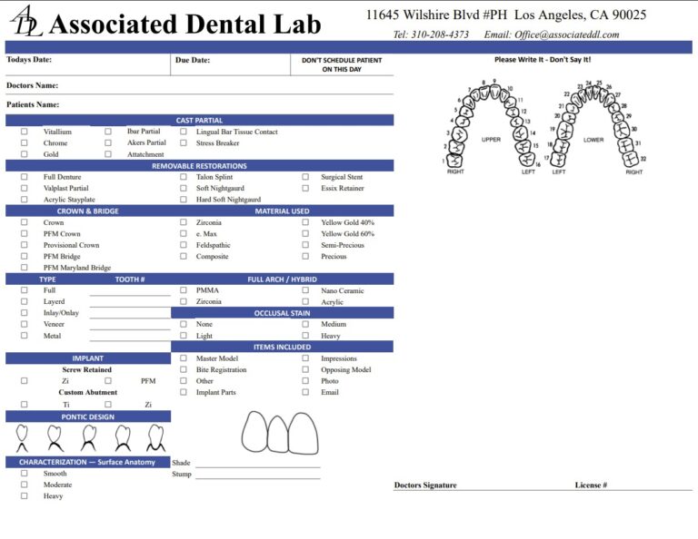
The “Send to Lab” checklist: what to include so the lab can succeed
Even excellent scans can stall if the lab lacks one key detail. Use this list for every implant scan submission:
- Implant system, platform, and level (implant-level vs abutment-level).
- Exact implant scan body used (brand, platform, height).
- Library note (scan body compatibility and version if known).
- Full-arch implant scanning tips applied (if it’s a full arch): include extra photos and bite records.
- If tissue is deep: include a PA confirming scan body seating when appropriate.
- Any special design notes: screw-retained vs cement-retained, emergence profile goals, provisional copy request.
Associated Dental Lab’s “Send a Case” page notes compatibility with major scanning systems (including DS Core, DEXIS, iTero, Medit, Trios) and provides guidance for exporting STL files and uploading through their account portal for systems without direct integration.
FAQ: Scan Body Torque & Handling
1) What scan body torque should I use for an implant scan body?
Scan body torque is manufacturer-specific. Some systems instruct hand-tightening, while others specify a maximum tightening torque (for example, max 15 N·cm) or a tightening range such as 10–15 N·cm for certain scan bodies. Always follow the implant scan body IFU and use the correct driver.
2) Can over-tightening scan body torque reduce accuracy?
It can. Research indicates that torque value can influence scan body displacement during screw tightening, and tightening behavior can contribute to seating deviations. The goal is consistent seating, not maximum force.
3) How do I prevent scan body indexing errors with intraoral scan bodies?
Prevent scan body indexing errors by confirming full seating (no tissue trapped), verifying no rotational/vertical looseness, applying scan body torque per IFU, and capturing complete scan body surfaces so the software can match the library accurately.
4) Why does implant library accuracy depend on scan body compatibility?
The CAD software locates the implant by matching the scanned implant scan body mesh to a library file. If the wrong library or wrong scan body selection is used, the match can be incorrect. Studies show implant libraries and scanners can affect full-arch trueness, highlighting why implant library accuracy matters.
5) What are the best full-arch implant scanning tips when using multiple scan bodies?
Use anchors early and often, avoid a long single sweep, build overlap in segments, and capture scan bodies from multiple angles. Associated Dental Lab’s scan stitching guidance outlines practical ways to reduce drift in full arches.
6) If a scan looks good, can the implant scan body still be wrong?
Yes. Research shows that improperly scanned scan bodies and scan body image capture deficiency can create registration errors in CAD matching even when the overall scan looks acceptable. If in doubt, re-seat, re-tighten to the correct scan body torque, and re-scan the scan body.
7) Should I list scan body details on the lab Rx?
Yes. Associated Dental Lab recommends listing the implant brand, platform, and the exact scan-body/library on implant prescriptions to prevent delays and mismatches. This directly supports scan body compatibility and implant library accuracy.
Conclusion
Digital implant workflows can be incredibly efficient, but they are unforgiving of small errors. The implant scan body is the cornerstone of accuracy, and scan body torque plus scan body handling determine whether that cornerstone is stable. When you tighten consistently within IFU limits, verify seating and stability, capture complete scan body geometry, and protect scan body compatibility and implant library accuracy, you reduce scan body indexing errors and make your lab’s job straightforward.
The result is what every practice wants: fewer remakes, fewer emergency adjustment appointments, and more predictable seats—especially in multi-unit and full-arch cases where errors compound. Make this checklist a habit, and your implant digital impressions will become more boring (in the best way).
About Associated Dental Lab
Associated Dental Lab is a dentists’ trusted Full-Service Dental Lab in Los Angeles, crafting smiles since 1962. They support digital workflows for implant cases, accept major scan platforms, and provide straightforward submission pathways (including uploading STL files when your scanner doesn’t have a direct portal connection).
If you want a lab partner who helps you reduce scan errors, standardize communication, and keep implant cases moving, contact Associated Dental Lab.