Implant restorations live or die on small details. Among the most critical—and most overlooked—are the implant scan body library you use and the real-world scan body compatibility between components, software, and manufacturing. Get those wrong and you’ll chase phantom errors: rotated fixtures in CAD, contacts that don’t exist clinically, screw channels a half-millimeter off. Get them right and cases drop in with a satisfying “click.”
This lab-informed guide clarifies how libraries actually work, why dental library version control matters, where scan body mismatch errors come from, and how “mixing brands scan bodies” can quietly sabotage scan body accuracy implants—especially across CAD/CAM implant libraries and different implant system compatibility claims. We’ll finish with a practical, step-by-step playbook and a tight QA checklist your team can use tomorrow.
The Implant Scan Body Library: What It Is (and Isn’t)
What a library really contains
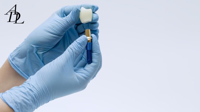
An implant scan body library is a set of CAD descriptors: the scan body’s exact geometry, the implant interface details (connection, rotational index), and the family of compatible components (e.g., Ti-bases, multi-unit abutments). Libraries translate the mesh you scan into a virtual implant position that downstream tools can use for design and CAM.
Modern systems (3Shape, exocad, Dental Wings) distribute official, frequently refreshed implant libraries. These include scan bodies, Ti-bases, stock and custom abutments, and multi-units—updated as vendors release new parts. exocad
Why “version control” is not optional
Vendors update libraries to fix small geometry offsets, add screw-access vectors, or correct implant connection metadata. Relying on stale versions can produce subtle, case-killing errors (e.g., platform level off by 0.1–0.2 mm, incorrect anti-rotation indexing). Implant manufacturers and third-party providers publish dedicated installers and update logs; labs should standardize update cadence and record versions used per case. DESS USA
Accuracy Traps: Where Scan Body Errors Come From
1) Improperly scanned scan bodies
Peer-reviewed work shows that incompletely captured or distorted scan body images degrade the virtual implant pose: think angular error, vertical drift, or rotation—each enough to move a screw access or change proximal contacts. PMC
2) Wear, alterations, and repeated use
Material and construction matter. Studies report differences in transfer accuracy between titanium, PEEK, and hybrid PEEK-on-titanium scan bodies; repeated use, micro-damage, and microscopic mismatches between parts can reduce trueness. Outcome: an implant plotted a fraction of a degree off becomes a crown that feels “almost right”—until torque day.
3) Geometry and height effects
Scan body geometry—including height—affects detection and trueness in IOS. Experimental studies demonstrate measurable differences in accuracy tied to design and dimensional features; choose the scan body indicated for the clinical depth and tissue level you’re scanning. Nature
4) Library/IOL (implant library) influence
The library itself influences trueness. Evaluations comparing different scanners and implant libraries found that the choice of library impacted geometric accuracy of the virtual implant. Translation: even with a perfect scan, using the wrong (or outdated) library can yield the wrong pose.
5) Cross-brand assumptions
Some components are cross-compatible in principle (platform dimensions, screw threads), but “works together” is not the same as “is dimensionally identical in CAD.” Older literature shows limited cross-manufacturer compatibility at the component level, yet modern digital tolerances and library metadata add complexity—so mixing brands without validated libraries can compound error.
Scan Body Compatibility: What “Compatible” Must Mean in 2025
To be clinically reliable, scan body compatibility must satisfy four layers—hardware, optical, software, and CAM:
- Hardware seating: exact connection fit, full seating verified radiographically if indicated.
- Optical detectability: material and surface texture scannable without glare or “washout.”
- Software/library mapping: the installed library exactly matches the physical scan body SKU and version.
- Downstream CAM footing: the chosen Ti-base or abutment exists in the same library family, with the same coordinate system and indexing.
Implant software vendors and manufacturers publish official installers and import guides (e.g., 3Shape Control Panel imports, exocad library integration) and maintain daily/regular updates. Use them, and record the version used per case.
Mixing Brands Scan Bodies: When It’s Smart—and When It’s a Setup for Failure
Smart mixing (with validation)
- You are using a third-party scan body and its official library that explicitly maps to your implant system and the Ti-base/abutment you plan to seat.
- Your lab has seat-tested the scan body in a training block or on a printed verification model before broad adoption.
Risky mixing (common “gotchas”)
- “It fits chairside” but the CAD library is for a different revision of the scan body—result: subtle angular/vertical offsets.
- Using a scan body from brand A, a Ti-base from brand B, and an implant from brand C without a single, matched library path. (Analog compatibility does not imply digital congruence.)
- Re-using worn PEEK scan bodies beyond their validated cycles—small tolerances, big headaches.
A recent scoping and in-vitro literature trend reinforces that deviations in geometry, library mismatches, and operator technique are key sources of error—especially in multi-unit and full-arch scenarios. Frontiers
Version Control in the Wild: A Simple Policy That Prevents Remakes
The 6-point library policy
- Source of truth: Only install libraries from official vendor pages or the implant manufacturer. Keep a whitelist (URLs + last checked).
- Case logging: Record library name + version + install date on every implant Rx (clinic & lab).
- One-case/one-version: Never mix library versions mid-case; if you must update, document and re-validate with the lab.
- SKU lock: The scan body’s physical SKU must match the library’s model ID (height, diameter, connection).
- Periodic audits: Quarterly checksum—uninstall or archive obsolete libraries; confirm current vendor releases.
- Seat-test: For any new brand, print a verification model or use a training block to confirm pose and screw-access alignment before real patient cases.
Installation hygiene
3Shape and exocad have clear, published import workflows (Control Panel “Import/Export” for 3Shape; exocad’s library integration and updates). Train your team on the same clicks every time; document with screenshots in your SOP.
How Scan Strategy and Isolation Interact with Libraries
Even with pristine libraries, scanning technique governs scan body accuracy implants:
- Dry field, matte surface: Reduce glare and reflection on titanium; consider scanning sprays only if the manufacturer allows.
- 360° data: Capture the entire cylindrical body, anti-rotational features, and hex flats; thin “slices” cause the software to guess.
- Stability: Avoid bumping the scan body; micro-rotation between buccal and lingual passes can introduce angular error in the merged mesh.
- Re-scan wisely: Patch small voids; don’t restart a whole arch unless necessary—stitching artifacts accumulate.
A 2024 systematic review and recent experimental studies underline scanner choice, scan body design, and workflow as key determinants of accuracy; these factors compound in complex or long-span cases.
CAD/CAM Implant Libraries: Practical Differences That Matter
Not all CAD/CAM implant libraries are equal on day-one install:
- Update cadence: Some vendors push daily/weekly updates; others bundle quarterly. Faster cadences catch post-release fixes sooner.
- Breadth of parts: “Official” libraries may include only the manufacturer’s parts; third-party libraries can add Ti-bases and multi-units across systems (great—if validated).
- Metadata completeness: Properly defined screw-access vectors, emergence profiles, and milling clearances reduce manual edits and CAM warnings.
Free, vendor-maintained libraries from established providers (e.g., DESS) publish exact reference tables and platform mappings—useful for verifying that your physical scan body is the same generation the library expects.
Step-By-Step: A Lab-Aligned Scan-to-Seat Workflow That Avoids Traps
Clinic steps
- Confirm hardware
- Verify implant system, platform, and connection. Select the exact scan body height/diameter for that platform (document SKU).
- Install/confirm libraries
- Clinic and lab align on the same implant scan body library version; take a screenshot of the library info panel and attach to the Rx.
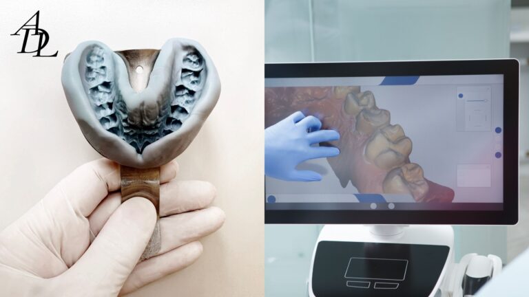
- Scan protocol
- Dry field; scan opposing and bite records; complete 360° capture of scan body. If reflections appear, adjust angle or lighting.
- Quick audit before sending
- Check for stitching seams, “flat spots,” or truncated chamfers on the scan body; re-scan locally if needed. Evidence shows improperly scanned bodies degrade virtual pose accuracy.
Lab steps
- Library validation at intake
- Open order → confirm library name/version equals clinic’s. If mismatch, pause and request approval to install/align.
- Pose check
- After alignment, verify axis, depth, and rotation; compare to expected screw-access direction. (Library selection itself influences trueness.)
- Provisional prototype (when indicated)
- For multi-unit or esthetic cases, consider a printed verification model or PMMA prototype to confirm access and contacts before final.
- CAM with matched components
- Ensure the selected Ti-base/abutment in CAD is from the same library family as the scan body. Avoid cross-brand mashups unless you’ve validated them.
- QC & documentation
- Export a brief QC sheet (library version, part numbers, screw torque plan). Archive with date/time stamps.
Troubleshooting: Symptom → Likely Cause → Fix
- Screw channel off-center → Mixed library versions or wrong scan body height/diameter; reinstall correct library; re-align.
- Crown rotates or won’t fully seat on Ti-base → Library and physical Ti-base are from different brands/editions; select matched components or validated cross-compatibility set.
- Open contacts that weren’t open in CAD → Angular error from incomplete scan body capture; re-scan and ensure 360° geometry; check scan body wear.
- Multi-unit bridge misfit → Mixing brands scan bodies across sites; library mismatch across units; print verification model or splint scan bodies for a new scan if indicated. Literature flags geometry variability and mismatches as key drivers in multi-unit error.
Special Cases
Bone- vs tissue-level, and scan body height
Scan body height and design should reflect soft-tissue thickness and scanner line-of-sight. Studies tracking implant level and scan body height show measurable effects on digital impression accuracy—choose the indicated height and avoid ultra-short bodies if tissue blocks visualization.
Reuse policy for PEEK bodies
Set a hard reuse limit; inspect for scratches, deformation, and discoloration. Repeated-use studies caution that hybrid constructions (PEEK on titanium base) can degrade transfer accuracy—rotate fresh devices into inventory.
Full-arch scans
Even with perfect libraries, operator and geometry factors compound across spans. Consider splinted scans, photogrammetry, or verification jigs; printed models for QC are inexpensive insurance. Recent work highlights variability and mismatch risk in full-arch implant scans.
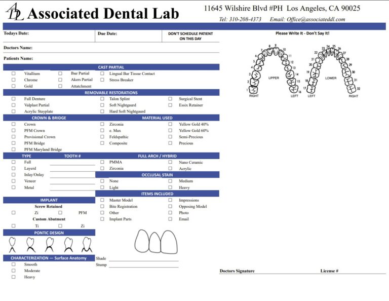
Documentation: The “No-Drama” Rx Block
- Implant system & platform (e.g., conical connection, internal hex)
- Scan body brand, SKU, height, and lot (photo of pack if possible)
- Library name & version (screenshot)
- Planned component (Ti-base/abutment) from the same library family
- Torque value and driver type
- Delivery date & whether printed verification is required
Associated Dental Lab’s “Send a Case” workflow makes attaching screenshots, photos, and notes straightforward—and the team can sanity-check your library details on intake.
Real-World Examples
Example 1: “It looked perfect in CAD, but the access is 0.5 mm off.”
Root cause: Scan body from Brand A; Ti-base from Brand B; library from Brand C. The rotational index differed by less than a degree—enough to displace the screw channel. Fix: single-family library path with verified parts; print a quick verification model for the re-do.
Example 2: “Contacts open after tightening.”
Root cause: Slight angular error from a partially scanned body; library correctly installed. Fix: re-scan with full 360° capture; replace worn PEEK body; repeat alignment. Study data link improperly scanned bodies with degraded virtual pose.
Example 3: “Multi-unit full-arch—why is everything drifting?”
Root cause: Cross-site variation in scan body geometry and operator stitching, compounded by library inconsistencies. Fix: single-brand scan bodies, validated library set, splinted scans or photogrammetry, and printed verification before final. Literature flags geometry/mismatch as major full-arch risks.
Quality Assurance Checklist (Print This)
Before scanning
- Correct scan body SKU & height for the implant platform
- Scan body seated and finger-torqued; verify seating clinically/radiographically if needed
During scanning
- Dry field; 360° capture; confirm anti-rotational features are visible
- Buccal bite with tripodization to stabilize MIP
Before sending
- Attach library version screenshot; list implant & component SKUs
- Note torque plan and request printed verification if complex
At the lab
- Confirm identical library name/version; verify pose and screw-access direction
- If anything looks “off,” pause and contact the clinic
- Log versions in the case file for future remakes
Associated Dental Lab publishes features, turnaround options, and digital intake guidance; partner with technicians to institutionalize this checklist and reduce surprises.
Frequently Asked Questions (FAQ)
1) What is an implant scan body library and why should I care?
It’s the CAD definition of your scan body + implant interface that turns a scan into a virtual implant. The wrong or outdated library causes scan body mismatch errors and inaccurate positioning. Vendors and manufacturers provide official installers and regular updates—use them.
2) How do I ensure scan body compatibility across systems?
Match the physical scan body SKU and height to the exact library entry; keep clinic and lab on the same version; and select Ti-bases/abutments from the same library family. Avoid unvalidated cross-brand mixes.
3) Do different CAD/CAM implant libraries change accuracy?
Yes. Research shows the chosen implant library can influence trueness—even with a clean scan. Align with your lab on the specific library version before design.
4) Can I re-use PEEK scan bodies indefinitely?
No. Repeated-use and hybrid constructions (PEEK on titanium) can introduce errors. Rotate fresh devices and inspect for wear.
5) Are certain scan body geometries more accurate?
Studies suggest geometry and height affect IOS trueness. Use the manufacturer-indicated geometry/height for the clinical situation and ensure complete 360° capture.
6) We “mix brands.” Is that always a problem?
Not always—but only do so with validated libraries that explicitly map scan body → implant → Ti-base within one consistent dataset. Otherwise, small rotational or vertical mismatches appear at delivery.
7) What if my library tools are outdated?
Install current packages from official sources (3Shape Control Panel imports, exocad integrations), document versions on the Rx, and standardize quarterly audits with your lab.
Conclusion
When implant cases go sideways, it’s rarely the ceramic—it’s the data chain. Treat the implant scan body library as a regulated device in your digital stack: control versions, lock SKUs, and validate scan body compatibility from scan to seat. Don’t gamble with “it should fit.” Align on one library family, install from official sources, scan meticulously, and verify complex cases with a quick printed check. Do these small things consistently and you’ll see fewer adjustments, tighter screw access, and more first-try seats.
About Associated Dental Lab
Associated Dental Lab is a dentists’ trusted Full-Service Dental Lab in Los Angeles. They accept digital impressions from major scanners, offer local pickup and prepaid shipping, and fabricate in-house with consistent turnaround times. If you want a partner who will sanity-check implant system compatibility, validate CAD/CAM implant libraries, and help you avoid scan body mismatch errors, contact Associated Dental Lab and send your next case with confidence.